
EB-2023-0676 | October 2023
Working on Solar Wiring and Fusing
Introduction
Knowledge of electrical circuits and wiring is key to installing a safe and efficient solar photovoltaic (PV) system. Many prospective PV system owners wrongly believe that electrical integration will be a simple do-it-yourself project with little to no danger posed to equipment or person. The truth is, however, that improper electrical integration can have significant consequences, including poor system performance, component damage, and/or electrical safety hazards.
Wiring and overcurrent protection devices (such as fuses and circuit breakers) can be sized, selected and integrated with your solar PV system once the solar array and other electrical devices (e.g., inverter, combiner box, disconnects) have been configured. And since there are many different ways to configure a solar PV system, electrical integration requires a careful calculation of circuit parameters, including voltage and current.
As such, this publication explores some of the essential considerations for wiring a solar PV system, including important requirements for voltage, ampacity, voltage drop, and circuit length. In doing so, the system should be designed by safely sizing wires and overcurrent protection devices – while being mindful of the trade-off between system voltage, wire length, line losses, and system cost. PV systems must also be installed in accordance with any federal and local regulations. The majority of the regulations governing solar PV are found in Article 690, “Solar Photovoltaic Systems,” of the National Fire Protection Association (NFPA) 70: National Electrical Code® (NEC®). The NEC® is a nationally recognized standard on safe electrical installation practice and is used as the governing electrical code in most jurisdictions in the U.S. (Note: other countries and jurisdictions may have different requirements; please consult your local Authority Having Jurisdiction (AHJ) for specific regulations.) It should be noted that while the NEC® is the leading resource and authority on electrical Working on Solar Wiring and Fusing safety, it’s not a design tool for increasing PV output, nor is it intended to serve as an instruction manual for untrained or unqualified persons.
Before purchasing any wiring or overcurrent protection for your electrical installation, you and/or your contractor should be proficient in using the wire tables and rules laid out in the NEC®. It’s also important to find out which version of the NEC® your local authorities plan to enforce, as the code is revised every few years with different inspection agencies invariably using different editions. A building inspector will not approve an installation that doesn't meet NEC® standards.
For these reasons, you should, and may be required to, consult a licensed electrician, solar professional, or your local AHJ before designing and installing a solar electric system. Qualified installers must understand all applicable electrical codes, regulations, and recommendations, including safe working and installation practices for code-compliant electrical integration.
Understanding Solar Circuits
Types of Circuits
A solar PV system can be organized into several functional circuits. The electrical characteristics and wiring of each section can be addressed in turn. The 2023 NEC® (NFPA, 2022) defines much of the essential terminology pertaining to electrical systems, components, and circuits in Article 100 and covers solar PV systems specifically in Article 690, Part I. Most PV circuits are easily distinguishable, though a few may require particular attention when referencing the code.
A simple grid-tied system, as depicted in Figure 2, may include:
- a PV source circuit with conductors between the solar modules (panels) and combiner box;
- a PV output circuit with conductors between the combiner box and DC disconnect;
- an inverter input circuit with conductors between the array disconnect and inverter; and
- an inverter output circuit with conductors between the inverter and the remaining AC system components. Additional circuits may exist depending on the system size, configuration and design. These additional circuits are typically named as inputs or outputs of particular components of the system (e.g., battery bank output circuit).
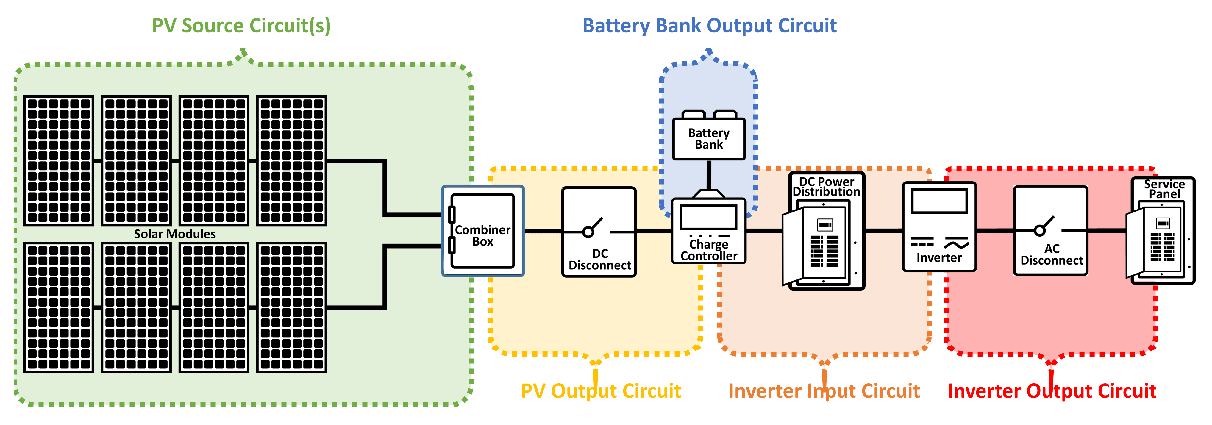
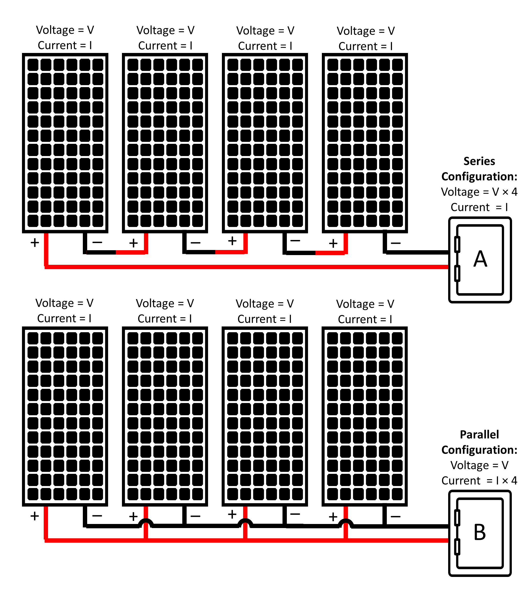
A PV source circuit consists of all the connections made between individual PV modules, with the electrical conductors eventually connecting to a combiner box where parallel connections are made. PV modules are often connected in series with one another to form these circuits (i.e., strings) that summate the electrical voltage of each PV module (Figure 3A, top). The parallel connections made within the combiner box will then summate the electrical current of each circuit that’s connected (Figure 3B, bottom). Smaller systems may only have one PV source circuit, while larger systems may be composed of several parallel PV source circuits.
PV output circuits, on the other hand, generally begin at the output of a combiner box. If a pass through box were used in place of the combiner box (i.e., transitioning into conduit without combining), then the output would still be considered a PV source circuit. The conductors forming the PV output circuit will typically connect to the DC utilization equipment or DC power distribution panel.
While the array side of the DC disconnect is considered a PV output circuit, the inverter side of the DC disconnect may be considered an inverter input circuit for some system configurations. With interactive systems, the PV output circuit and inverter input circuit will essentially be the same because the electrical characteristics are the same on either side of the DC disconnect.
An inverter output circuit generally runs from the inverter's AC output to the main service panel, with its conductors usually running through conduit, such as electrical metallic tubing (EMT) or liquid-tight flexible non-metallic conduit (LNFC).
Types of Conductors
When designing a PV system, the type of wire must be considered for each circuit. Electrical conductors (i.e., wires) are made with different conducting materials, stranding, and insulation. It’s important to select the correct wire type for each application to ensure long-term reliability and safety.
Aluminum and copper are the most common conductors in residential and commercial wiring. Aluminum is used in many utility and commercial applications due to its lower cost, but is not allowed in residential applications as smaller aluminum wires can be more easily damaged during installation, with higher rates of failure at their points of connection potentially causing fires. Copper, on the other hand, is more conductive (i.e., carries more current) and stronger than aluminum.
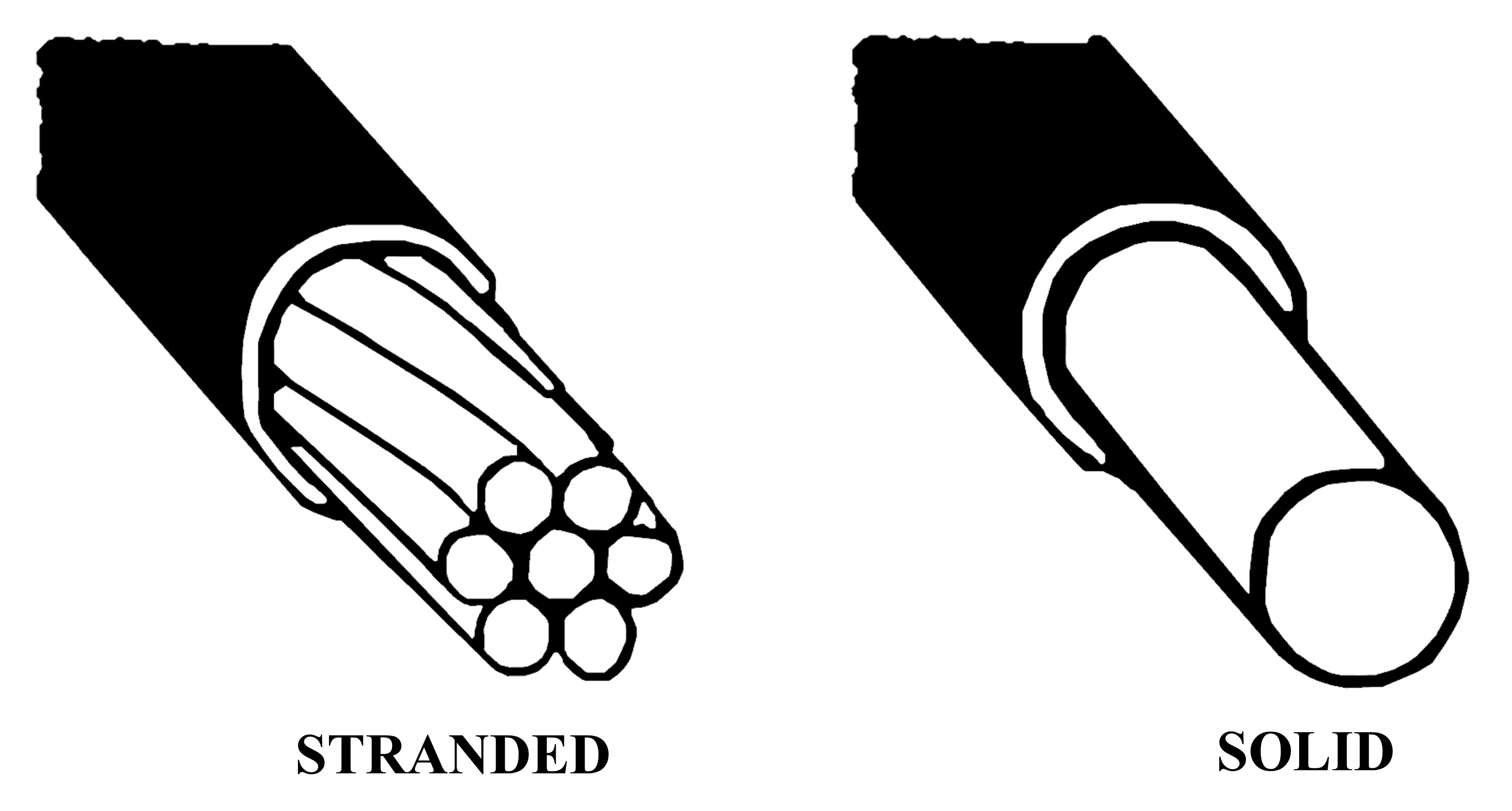
Wiring is also available in solid and stranded forms as shown in Figure 4. Solid wire is heavier, made for all-weather conditions, is anti-corrosive, rugged, and can withstand frequent, but minimal movement. Its long-lasting durability, minimal movement, and ability to carry a higher current than stranded wire (having the same diameter) make it an ideal option for household AC wiring. Stranded wires, on the other hand, are made by twisting multiple small conductors together. Stranded wire is more flexible than solid wire, making it easier to work with and less likely to break due to movement or vibration. However, stranded wire has higher resistance to current flow (as will be discussed later), since the cross-section of a stranded conductor contains air in addition to the metal strands.
Wire Insulation and Color Code
The insulation surrounding a conductor protects it from damage and prevents the electrical current from transferring to surrounding material. The type of insulation surrounding the conductor will vary based on each segment of the PV system. NEC® Table 310.4(1) provides more details on the ratings and uses of various conductor and insulation types.
Table 1 summarizes the most common types of wire insulation in PV systems. For example, THHN is rated for dry indoor areas; THWN is rated for indoor areas and conduit for wet and outdoor areas; and UF and USE are rated for underground and damp areas.
|
Application |
Required Resistances |
Conductors |
Installation |
Recommended Insulation Type |
|||||
|---|---|---|---|---|---|---|---|---|---|
| Moisture | Sunlight | 90°C | Fire | One | Multiple | Exposed | Conduit | ||
| PV Source | ✓ | ✓ | ✓ | ✓ | ✓ | ✓ | USE-2, PV wire | ||
| PV Output | ✓ | ✓ | ✓ | ✓ | USE-2, XHHW-2, RHW-2, THWN-2 | ||||
| Interior | ✓ | ✓ | ✓ | THHN, THW, RHW, XHHW, RH | |||||
| Interior | ✓ | ✓ | ✓ | NM, NMB, UF | |||||
| Battery | ✓ | ✓ | ✓ | USE, RHW, THW | |||||
PV source circuit conductors are typically exposed to the elements since solar arrays are installed either on rooftops or somewhere in the field. PV wire and USE-2 wire are commonly used for PV source circuits as they can both be installed outdoors. Both wire types have similar electrical ratings and requirements, including UV and moisture resistance, as well as a high ambient heat rating of 90°C (194°F).
While the jackets around USE-2 and PV wire can both handle extreme UV exposure, PV wire has thicker insulation for added mechanical protection against physical abuse. Both wire types are suitable for the DC circuits of a PV array in accordance with Subsection 690.31(C) of the 2023 NEC®.
A less expensive building wire can be installed on the other side of the junction or combiner box. THWN-2 and XHHW-2, for example, can be used for the PV output circuit, but should always run in conduit when used outdoors as they’re not UV-resistant. Both wire types can withstand high heat and wet conditions that could result from condensation. While THWN‑2 can be run all the way from the junction box, or combiner box, to the main AC service panel, a different wire size may be necessary in the inverter output circuit to account for changes in the AC voltage and current.
Wires are also color-coded by use and function as summarized in Table 2. Direct current (DC) and alternating current (AC) wires have different color-coding requirements in the U.S., requring an understanding and awareness of the different types commonly encountered in PV systems. Figure 5 shows an example of the different types of conductors in an ungrounded PV system. Like all electrical circuits, one conductor (wire) must run from the power source (i.e., module or array) to the load center (i.e., main service panel), while another conductor will theoretically carry the electrons back to the source.
| Conductor | DC System, Negative Grounded | DC System, Ungrounded | AC System |
|---|---|---|---|
| Ungrounded | Positive=Red* | Positive=Red; Negative=Black* | L1=Black; L2=Red; L3=Blue |
| Grounded | Negative=White, Gray | N/A | Neutral=White |
| Grounding | Green, Green/Yellow, Bare | Green, Green/Yellow, Bare | Green, Green/Yellow, Bare |
| *not required, but common | |||
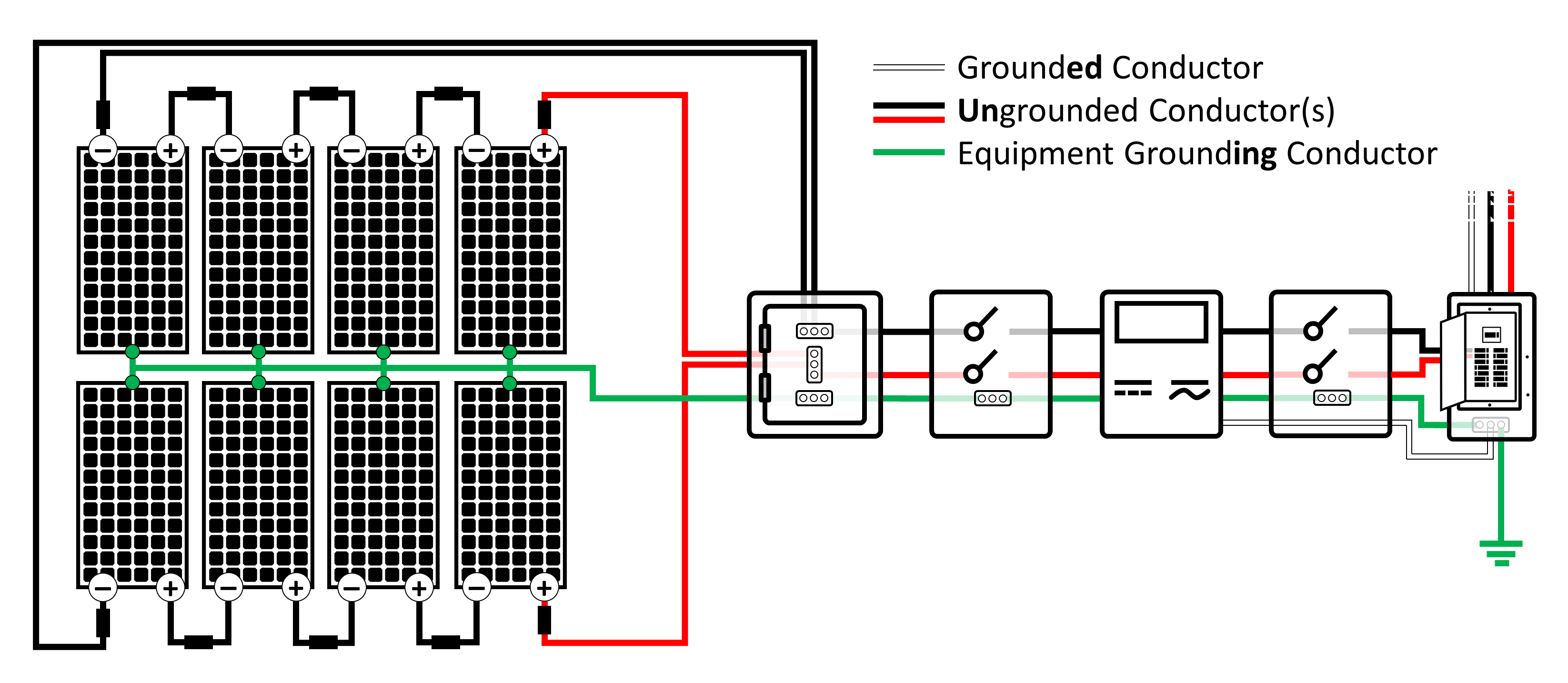
The grounded conductor is a current-carrying conductor that is intentionally referenced to the earth (i.e., ground). This is often accomplished by connecting or bonding the grounded conductor to a copper-coated rod driven into the earth in order to establish a reference voltage and/or to reduce the risk of electrical shock from a fault current. Examples of a grounded conductor are the negative conductors in many DC systems and the neutral conductors in AC wiring. The grounded conductor must be either white or gray in a grounded system. An ungrounded DC system, on the other hand, will have no DC grounded conductor since an ungrounded inverter technically has no DC “system” grounding.
An ungrounded conductor is a current-carrying conductor that is not grounded. The ungrounded conductor is typically the positive in a grounded DC system, but both conductors will be ungrounded, or “hot,” when working in an ungrounded DC system (i.e., transformerless inverter). While many colors can be used for the ungrounded conductor (except white, gray, green, or bare copper), red wires are typically used for the DC positive, while black is used for the ungrounded DC negative. Hot AC lines, on the other hand, use black for line 1, red for line 2, and blue for line 3 (for three phase systems).
Note that if the proper color of insulation is unavailable for a particular application, it is acceptable in the NEC® to color-code, or mark, all ends of the wire with UL listed electrical tape or paint.
A grounding conductor, or equipment grounding conductor (EGC), is not meant to carry current. The EGC connects (bonds) all the metal equipment and electrical hardware to the earth ground so that there are no dangerous voltage differences. Only when a live (hot) wire shorts into a metal component will electricity "conduct" through the EGC and into the earth. The grounding conductor must be a green, green with yellow stripes, or bare copper wire.
Wire Connectors
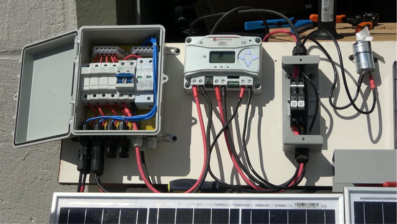
Most solar modules are manufactured with a few feet of PV wire already attached to their junction box on the backside of the module (Figure 6, left). A watertight connector will also be found on the end of each lead. The type of connector on the end of each lead will usually dictate the type of connectors that will be used for the rest of the circuit.
While several connector types are currently used in the PV industry, the most common is MC4 (representing the original manufacturer, Multi-Contact, with a 4 mm diameter contact pin). MC4 connectors come in male and female configurations (Figure 6, right). Care should be taken when pairing the male and female configurations, as some manufacturers classify these connectors by the format of the plastic insulator, while others classify the format by the metal contact found within the plastic insulator. This distinction is important because the male plastic insulator contains the female metal contact, while the female plastic insulator contains the male metal contact.

Wire Sizing
Properly-sized wires are important for the performance and safety of a PV system. Choosing the right wire size will help minimize the voltage drop and power loss within an electrical circuit while minimizing the risk of fire hazard and/or electrocution. Conductors should be properly-sized for each portion of the system to avoid any melting, fire, or other electrical problems. Wires are commonly sized to meet the minimum regulatory requirements of the NEC® while keeping installation costs to a minimum.
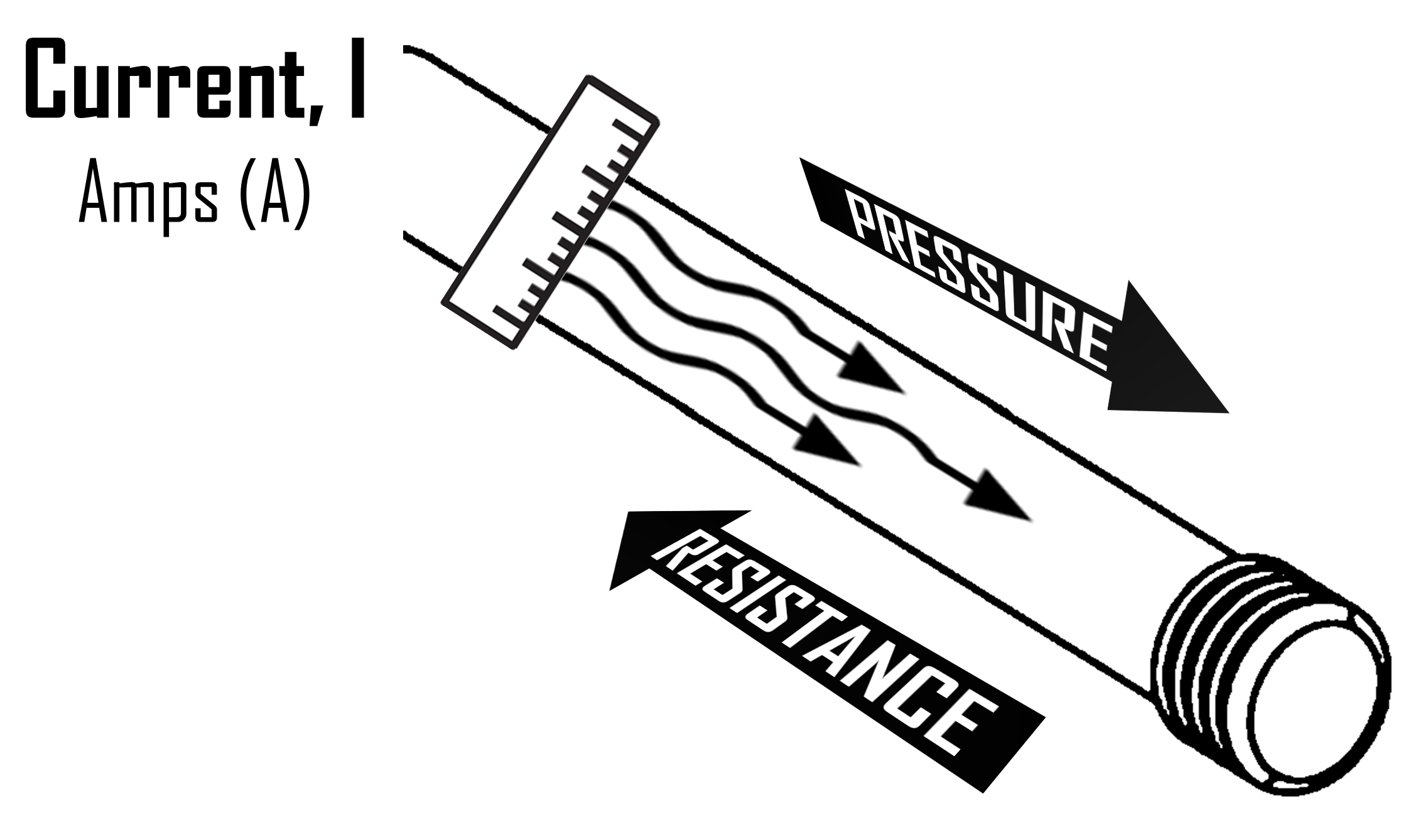
A conductor will carry electrical current much like a hose will carry water (see Figure 7). A larger hose will allow more water to flow through, with less resistance and pressure. An electrical current will behave in the same manner with larger conductors carrying more electrical current. A large conductor will generate less resistance and heat as a result. Conductors that are too small, on the other hand, will lead to increased resistance, heat gain, and power loss within the system. Undersized wires could heat up to the point of melting or burning (whether in normal operations or in abnormal overcurrent situations).
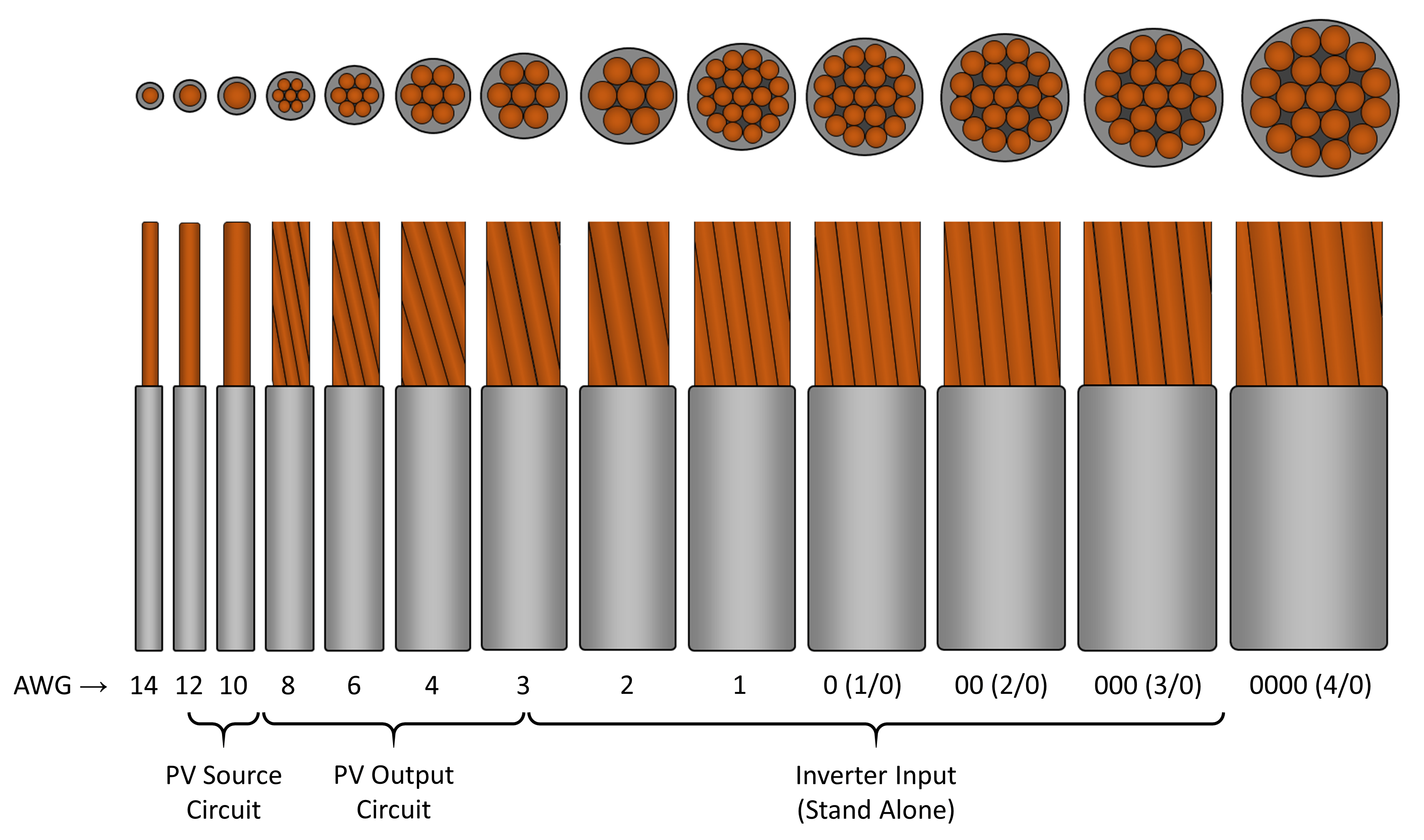
Wire gauge describes the thickness (or diameter) of the wire, and is designated by the American Wire Gauge (AWG) system. Although it seems counter-intuitive, larger conductors have smaller AWG numbers (see Figure 8). For instance, AWG 14 is thinner than AWG 1. Conductors larger than AWG 4/0 are generally identified by their cross-sectional area in thousands of circular mils (kcmil), where 1 kcmil = 0.5067 mm². A circular mil is the area of a wire one mil in diameter.
Conductor sizes for PV systems usually range from AWG 18 to 4/0 (which is pronounced “four-ought”). PV source circuits are commonly AWG 10 or 12 PV wire based on the size of the leads that are connected to the PV module(s). Most residential systems will use AWG 10 or 8 on the AC side. Bare copper equipment ground for the array is usually AWG 8 or 6, while battery bank wire size often varies from 1/0 (“one-ought”) to 4/0 (“four-ought”).
Wire sizing is based on the conductor’s current-carrying capability, or ampacity, measured in Amps (A). Ampacity describes the conductor’s ability to continuously carry an electrical current without exceeding its temperature rating. Ampacity is affected by conductor material (copper or aluminum), conductor size (gauge and length), insulation type, temperature, and wiring application (e.g., direct burial, conduit, free air).
The maximum permissible ampacity for each wire gauge is specified in the 2023 NEC® for current-carrying conductors in raceway, cable, or earth (directly buried) (Table 310.16), as well as single-insulated conductors in free air (Table 310.17). Table A1 provides an excerpt of these ampacity tables based on 30°C (86°F). Nominal ampacity is derated (reduced) for temperatures exceeding 30°C (86°F).
Additional circuit requirements for PV systems are addressed in Article 690, Part II of the 2023 NEC®, including maximum voltage (Section 690.7), circuit sizing and current (Section 690.8 (A) and (B)), and overcurrent protection (Section 690.9). Each of these is discussed in the sections below, along with important steps required for proper wiring.
Maximum Voltage [NEC® 690.7]
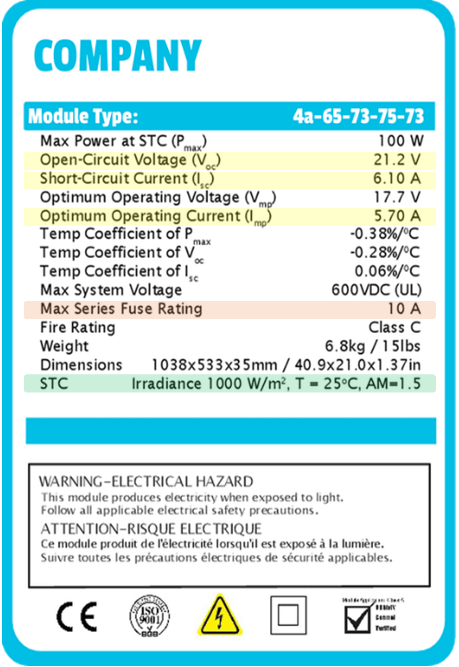
Step 1-1: Calculate maximum voltage. The voltage rating of a wire is the highest voltage than can be continuously applied to it. Voltage ratings are mainly dependent on the type of insulation around the wire which prevents sparks from jumping to another conductor. As detailed in Section 690.7 of the 2023 NEC®, the maximum DC voltage of a PV source circuit or PV output circuit is based on the total open-circuit voltage of the string of modules. The open-circuit voltage (Voc) of a PV module is specified on the data label that’s commonly affixed to the back of the module (Figure 9).
A voltage correction factor (CT) is needed, however, to account for the increased output voltage at those temperatures falling below the standard test conditions (STC) of 25°C (77°F). The NEC® suggests using the Extreme Annual Mean Minimum Design Dry Bulb Temperature from the ASHRAE Fundamentals Handbook (ASHRAE, 2017). The temperature correction factors provided in Table 3 should be used for crystalline silicon PV modules unless using the voltage-temperature coefficients provided by the manufacturer in accordance with Subsection 110.3(B) of the NEC®.
| Ambient Temperature (°C) | Ambient Temperature (°F) | Voltage Correction Factor, CV |
|---|---|---|
| 24 to 20 | 75.2 to 68 | 1.02 |
| 19 to 15 | 66.2 to 59 | 1.04 |
| 14 to 10 | 57.2 to 50 | 1.06 |
| 9 to 5 | 48.2 to 41 | 1.08 |
| 4 to 0 | 39.2 to 32 | 1.10 |
| -1 to -5 | 30.2 to 23 | 1.12 |
| -6 to -10 | 21.2 to 14 | 1.14 |
| -11 to -15 | 12.2 to 5 | 1.16 |
| -16 to -20 | 3.2 to -4 | 1.18 |
| -21 to -25 | -5.8 to -13 | 1.20 |
| -26 to -30 | -14.8 to -22 | 1.21 |
| -31 to -35 | -23.8 to -31 | 1.23 |
| -36 to -40 | -32.8 to -40 | 1.25 |
According to the guidelines in Subsection 690.7(A), the maximum PV system voltage (Vmax) can be calculated by multiplying the rated open-circuit voltage of a PV module (Voc), by the number of PV modules connected in series (ns), by the low-temperature voltage correction factor (CV) as follows:
Vmax = Voc × ns × Cv
Keep in mind, the maximum voltage for PV source and PV output circuits is 600 V for most residential applications in the U.S. See Subsection 690.7(2) for more information. The output-circuit voltage is acceptable if the maximum possible voltage is less than 600 V, provided that it does not exceed the rating of any connected component, including the modules, inverter, charge controller, disconnects, and conductors. A different set of requirements are required for commercial and utility-scale systems, which allow for 1,000 V and 1,500 V, respectively.
Maximum Current [NEC® 690.8(A)]
Step 2-1: Calculate maximum current. The maximum current flowing through a PV source, or PV output circuit, is based on the short-circuit current of the solar module(s) under STC. The short-circuit current (Isc) is usually found on the data sheet affixed to the back of the module (Figure 9). Remember, electrical current is additive for any PV modules or strings wired in parallel (Figure 3).
The maximum circuit current (Imax) of a PV source circuit, or PV output circuit, is calculated by multiplying the rated short-circuit current (Isc), or the sum of any parallel Isc, by an overcurrent safety factor (ηi) of 1.25 (125%) in order to account for any enhanced irradiance (i.e., lighting that is brighter than STC that will increase electrical current) as detailed in NEC® 690.8(A)(1)(a). Assuming all parallel strings have equal current, the short-circuit current (Isc) can simply be multiplied by the number of parallel modules or strings (np) as follows:
PV Source or Output: Imax = Isc × np × ηi
In addition to other circuit descriptions, previous NEC® versions specified maximum current for the inverter input circuit of a stand-alone, battery-based system. The maximum inverter input current will increase as battery voltage drops - with the inverter potentially demanding more current than the system can supply. The maximum current (Imax), or rated input of the inverter (Iin), in this case, is based on the inverter’s output power rating (P), minimum operating voltage (Vmin), and inverter efficiency (η) which are all commonly found in the manufacturer’s specification sheet. The resulting equation is expressed as follows:
Inverter Input: Imax = Iin = P ÷ Vmin ÷ η
The maximum current flowing through an inverter output circuit, on the other hand, will be based on the inverter’s continuous current output rating (Iout) in accordance with the 2023 NEC® 690.8(A)(1)(c).
If the continuous current output rating (Iout) of the inverter is not available in the inverter’s data sheet, or on the inverter itself, then it can be determined by dividing the inverter’s output power rating (P) by its operating voltage (VAC). The resulting equation can be expressed as follows:
Inverter Output: Imax = Iout = P ÷ VAC
Note, residential AC voltage is commonly 240 V for single phase electricity. While instantaneous or surge power ratings may specify higher electrical current for shorter time periods (less than three hours), wire sizes are based on continuous electrical current (greater than three hours) to permit sufficient time for the wires to heat up.
Conductor Ampacity [NEC® 690.8(B)]
Step 3-1: Calculate nominal ampacity. NEC® 690.8(B) provides further guidance to ensure wiring can handle continuous current (3 hours in duration). The circuit conductors must be sized to handle at least 125% of the maximum continuous current that was calculated previously. This 125% is in addition to the 125% used to estimate the maximum current under high irradiance. In this case, the nominal ampacity (Inom) is based on the maximum electrical current (Imax) multiplied by another safety factor (ηc) of 1.25 (125%) to account for continuous electrical current as follows:
Inom = Imax × 1.25
Step 3-2: Determine temperature correction factor. Cable ampacity should also be derated when the conductors experience higher temperatures. To derate for installation conditions, determine the hottest local temperature on record for your location (or what's called the “2% Average” temperature) using a temperature map. The hottest temperature recorded for Baltimore, as an example, is 34°C or 93.2°F (FSEC, 2023). Additional heat gain should also be considered, including the exposure of any raceways or cables to direct sunlight, as well as any conduit installed in close proximity to the roof.
Conductors will be hotter when exposed to direct sunlight or when installed on or above rooftops. In those cases, a temperature adder adjusts the ambient temperature in accordance with Subsection 310.15(B)(2) of the NEC®, which notes that “for raceways or cables exposed to direct sunlight on or above rooftops where the distance above the roof to the bottom of the raceway or cable is less than 19 mm (¾ in), a temperature adder of 33°C (60°F) shall be added to the outdoor temperature” (NFPA, 2022).
This temperature adder will increase the effective ambient temperature of your location. The location of an inverter could also influence temperature and heat gain within an inverter output circuit. Many commercial rooftop PV systems, for example, have roof-mounted inverters that require AC-side temperature derates.
Next, determine the temperature correction factor (CT) by referencing the adjusted temperature in Table 4. Ampacity will be reduced by the correction factor that corresponds to the elevated ambient temperature. An adjusted ambient temperature of 66°C (151°F), for example, would result in a ampacity correction factor of 0.58, assuming a THWN-2 wire rated at 90°C was used.
| Ambient Temperature | Temperature Correction Factor, CT | |||
|---|---|---|---|---|
| (°C) | (°F) | 60°C (140°F) Rated Conductor | 75°C (167°F) Rated Conductor | 90°C (194°F) Rated Conductor |
| 10 or less | 50 or less | 1.29 | 1.20 | 1.15 |
| 11 – 15 | 51 – 59 | 1.22 | 1.15 | 1.12 |
| 16 – 20 | 60 – 68 | 1.15 | 1.11 | 1.08 |
| 21 – 25 | 69 – 77 | 1.08 | 1.05 | 1.04 |
| 26 – 30 | 78 – 86 | 1.00 | 1.00 | 1.00 |
| 31 – 35 | 87 – 95 | 0.91 | 0.94 | 0.96 |
| 36 – 40 | 96 – 104 | 0.82 | 0.88 | 0.91 |
| 41 – 45 | 105 – 113 | 0.71 | 0.82 | 0.87 |
| 46 – 50 | 114 – 122 | 0.58 | 0.75 | 0.82 |
| 51 – 55 | 123 –131 | 0.41 | 0.67 | 0.76 |
| 56 – 60 | 132 – 140 | – | 0.58 | 0.71 |
| 61 – 65 | 141 – 149 | – | 0.33 | 0.65 |
| 66 – 70 | 150 – 158 | – | – | 0.58 |
| 71 – 75 | 159 – 176 | – | – | 0.50 |
| 76 – 80 | 168 – 176 | – | – | 0.41 |
| 81 – 85 | 177 – 185 | – | – | 0.29 |
Step 3-3: Determine conductor-in-conduit factor. Ampacity calculations must also account for any additional heat gain within conduit enclosure. Bundling current-carrying conductors into the same conduit affects their ability to dissipate heat. The ampacity is derated when more than three current-carrying conductors are installed in a single conduit or raceway that exceeds 24 inches in length. The more current-carrying conductors in conduit, the hotter it gets. Table 5 lists conduit adjustment factors (CC) corresponding to the number of current-carrying conducts in conduit.
| Number of Current-Carrying Conductors* | Conduit Adjustment Factor, CC |
|---|---|
| 1 – 3 | 1.00 |
| 4 – 6 | 0.80 |
| 7 – 9 | 0.70 |
| 10 – 20 | 0.50 |
| 21 – 30 | 0.45 |
| 31 – 40 | 0.40 |
| 41 and above | 0.35 |
| *Number of conductors is the total number of conductors in the raceway or cable, including spare conductors, but excluding conductors that are connected to electrical components that cannot be simultaneously energized. | |
No adjustments are needed with less than four wires in conduit. For example, a string of PV modules having only one set of conductors (i.e., one positive and one negative) will have an adjustment factor of 1.0 (100%). A system having more than three conductors, however, will increase the combined heat, thereby reducing the electrical current that can safely be carried. As an example, only 80% (0.8) of a conductor’s ampacity can be used when there are 6 current carrying conductors within a raceway.
Step 3-4: Derate nominal ampacity. After determining the temperature- and conduit-based correction factors, ampacity can be derated in accordance with NEC® 310.15 as follows:
Id = Inom ÷ CT ÷ CC
where: Id is the derated ampacity (A); Inom is the nominal current (A) calculated previously; CT is the temperature correction factor (from Table 4); and CC is the conduit correction factor (from Table 5).
Derated ampacity accounts for any deviations from reference temperatures; NEC® Tables 310.16 and 310.17 are referenced at 30°C. The minimum required conductor size will be based on this derated ampacity, with higher temperatures (i.e., more derating) increasing the required conductor size.
Step 3-5: Determine wire size. The required wire size for the PV system can now be determined using an ampacity chart. The maximum permissible ampacity for different wire gauge is specified in the 2023 NEC® for current-carrying conductors in raceway, cable, or earth (Table 310.16), as well as single-insulated conductors in free air (Table 310.17). Table A1(see Appendix) provides an excerpt of these ampacity tables based on 30°C (86°F).
Select the smallest wire size (largest AWG number) that meets or exceeds the derated ampacity of the circuit. This ensures that the conductor can safely conduct the maximum continuous current of a circuit with the appropriate margin of safety. A conductor carrying too much current could lead to heat gain that exceeds the temperature rating of the insulation. While the NEC® provides guidance on how to calculate this minimum wire gauge, a larger gauge can be used.
The ampacity chart for single-insulated conductors in free air (see Table A1 in Appendix), for example, specifies that AWG 10 THWN-2 copper wire rated for 90°C can handle up to 40 amps. Assuming a temperature-adjusted derated ampacity of 36.1 amps, then AWG 10 would be the minimum allowable wire size that could safely be used with that circuit.
Wire Length
Voltage drop is another important issue to consider, particularly with circuits having a low operating voltage and/or a long conductor run. Longer wire runs will result in higher electrical resistance and lower power output. An excessive voltage drop can adversely impact electrical devices and system components (e.g., batteries, charge controllers, inverters) that may require a minimum voltage for proper operation. An excessive voltage drop in AC circuits could also cause loads to operate improperly or hinder an interactive inverter’s ability to remain connected to the grid.
The largest voltage drop is often found in the PV output circuit, especially when the PV array is located far from the DC utilitization equipment, inverter, or charge controller. Since all the combined PV power flows through this wire run, the performance of the PV output circuit should be optimized. A maximum voltage drop of 3% of the operating voltage is recommended as an industry best practice for most PV system circuits in accordance with the informational note given in Section 210.19 of the NEC®.
Step 4-1: Determine the resistance of a conductor using Table A2 (see Appendix) based on the wire size (AWG or kcmil), conductor material (copper or aluminum), and conductor composition (stranded or solid). A circuit using stranded AWG 8 copper wire, for instance, would have a resistance of 0.778 ohms per kilofoot (Ω/ kft). For reference, a kilofoot equals 1,000 feet of wire.
Step 4-2: Calculate maximum operating current. The maximum operating current (Iop) for the PV source circuit is based on the optimum operating current (Imp) provided on the specification sheet of the PV module (Figure 9). PV output circuits must also account for the number of parallel modules or strings (np) within the array (current is additive for modules wired in parallel). The maximum operating current of the inverter output circuit is, likewise, based on the maximum AC current (Ipm) provided on the inverter’s specification sheet.
PV Source: Iop = Imp
PV Output: Iop = Imp × np
Inverter Output: Iop = Imp
Step 4-3: Determine the circuit length based on the total roundtrip flow of electrons through the circuit. In this case, the complete distance of each wire path (D) will include any module leads, wire extensions, wire runs (e.g., home run, near run), and/or wire bunching within electrical enclosures. PV source circuits must also account for the number of parallel modules or strings (np) within the array (each string has a wire run to the junction or combiner box).
To account for the circular flow of electrical current through a circuit, the total conductor length on the DC-side of the system is twice the length of the conductor run (one positive + one negative). The total conductor length on the AC-side of the system is two times the length for split-phase (line-to-neutral voltage with the two hots being 180 degrees out of phase), and 1.732 times the length for 3-phase (line-to-line voltage with the three hots being 120 degree out of phase).
PV Source or Output: L = 2 × D
Inverter Output (split phase): L = 2 × D Inverter
Output (3- phase): L = 1.732 × D
Step 4-4: Calculate the voltage drop (Vdrop) through a conductor based on its operating current (Iop), conductor resistance (R), and total circuit length (L) in accordance with Ohm’s law as follows:
Vdrop = Iop × R × L
Step 4-5: Calculate the percent voltage drop (V%) based on the voltage drop (Vdrop) and operating voltage (Vop) of the circuit as follows:
V% = 100 × Vdrop ÷ Vop
Installers have several options to lower this voltage drop if it exceeds industry recommendations of 3%, including shortening the length of conductor (L) if feasible. As an example, the inverter could be moved closer to the array. A shorter wire run will reduce the voltage drop in the circuit with fewer electrons lost to the wire’s natural resistance.
Circuit resistance can also be reduced using a larger conductor (likely exceeding the minimum size based on ampacity calculations), as well as by using fewer splices and connections in the circuit. Configuring a circuit with a higher voltage will also reduce its operating current while using smaller conductors to deliver the same level of power in accordance with Watt’s Law (P=V×I).
Overcurrent Protection
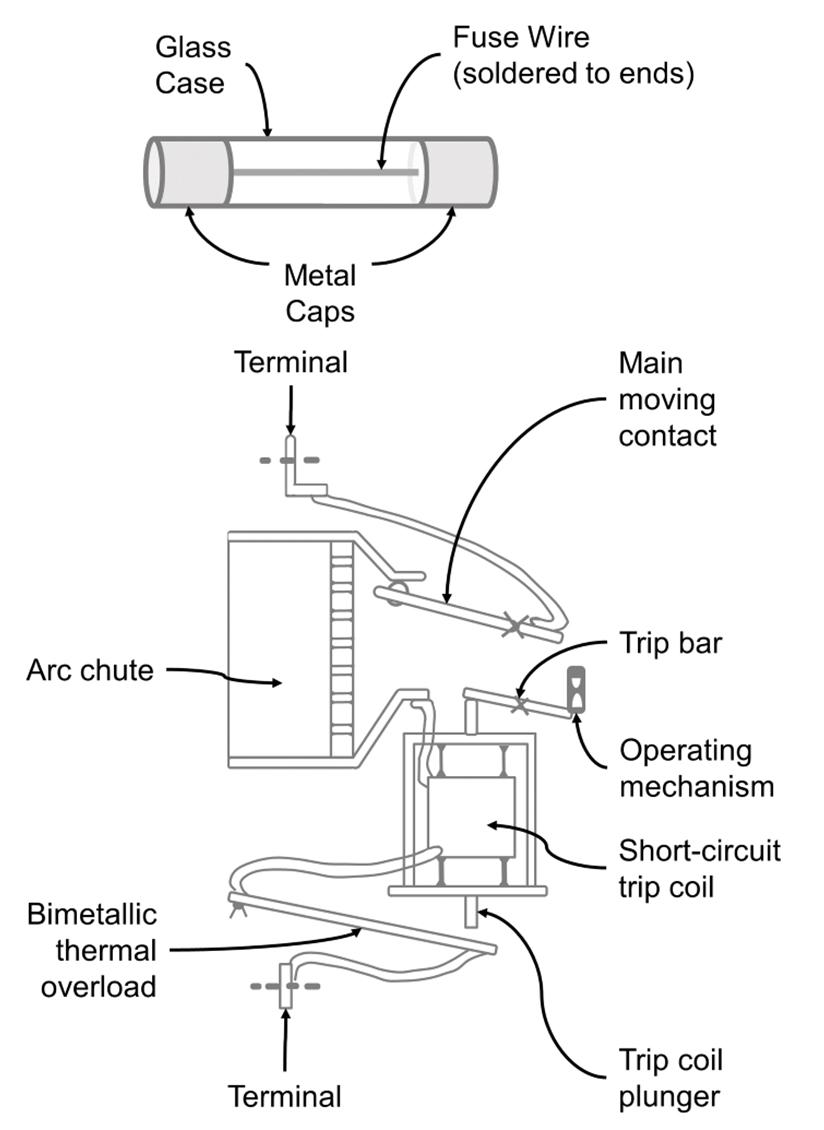
General information on overcurrent protection is provided in Article 240 of the NEC®, while Section 690.9 provides further guidance on overcurrent protection within PV systems. An overcurrent protection device (OCPD) protects conductors and equipment from overcurrent by opening (i.e., turning off) the circuit whenever the electrical current is too high. OCPDs can keep you and your system safe by preventing overcurrent and overheating which could damage conductor insulation, cause electrical shock, and/or result in fire. An overcurrent condition can be the result of an overload, ground fault, or short circuit.
OCPDs include fuses and circuit breakers (Figure 10). A fuse contains a thin metallic conductor that melts when the electrical current exceeds its rating. Fuses stop the flow of electricity (open the circuit) when excess current is forced through the circuit. A circuit breaker, on the other hand, is an electrical switch that automatically opens for overcurrent protection, and manually opens as a means of circuit disconnection. Circuit breakers have the advantage of being resettable after an overcurrent trip and can be used as circuit disconnects for installation and maintenance.
Circuits and Equipment [NEC® 690.9(A)]
Subsection 690.9(A) of the NEC® requires overcurrent protection for DC circuits, and inverter output circuits, if the maximum potential current exceeds the maximum amount of current that can safely flow through the circuit. This includes conductors and equipment within the PV source, PV output, inverter output, and/or battery or load circuits. Each circuit will generally be protected from any, and all, connected power sources, particularly those with the potential for high back-feed currents (e.g., battery banks).
As such, OCPDs are required to protect conductors and PV modules from line-line, line-ground, and mismatch faults. OCPDs will prevent excessive current from backfeeding (flowing backwards) into a shorted PV module if it stopped producing electricity due to any damage or shading. While grounded conductors don’t normally include overcurrent protection (as opening the circuit would disconnect the system from ground), ungrounded conductors will be protected in most systems (with exceptions for some PV source and output circuits).
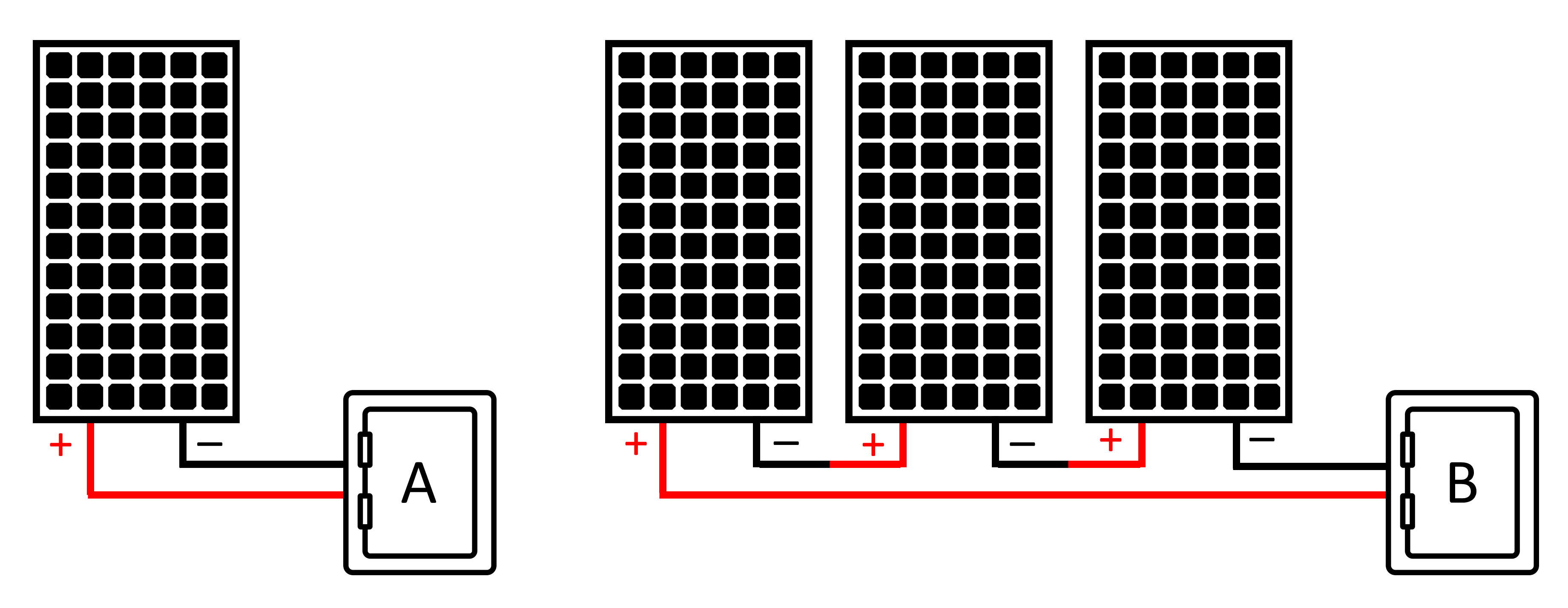
Single Series String: OCPDs are not required for single source circuits which preclude connections to external power sources (e.g., parallel source circuit, battery, inverter backfeed), provided the conductors are properly sized for the greatest amount of current that the single source circuit is capable of producing. See nominal ampacity calculations in Step #3-1.
A single PV module, for example, poses no risk of fire if it short circuits since PV modules are inherently current-limited and there are no other sources of current for it to absorb. A series-connected PV module, will likewise, pose no risk of overheating since the short circuit current from the previous module within the series will not exceed the maximum series fuse rating of the shorted module (see Figure 11).
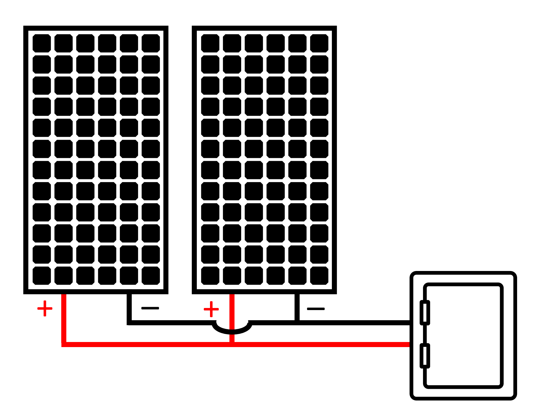
Two Parallel Strings: A solar array having two identical source circuits (Figure 12), likewise, does not require overcurrent protection assuming each source circuit is sized to handle its own maximum current. If one module were to experience a short circuit, the short circuit current from the functioning module would flow into the faulty module. But, there would not be enough current to push past the shorted panel’s maximum series fuse rating.
As detailed in NEC® 690.9(A)(1), no OCPD is required, in this case, as long as the remaining short-circuit current does not exceed the ampacity of the conductors (see nominal ampacity calculations in Step #3-1) or the maximum series fuse rating specified on the module nameplate (see Figure 11).
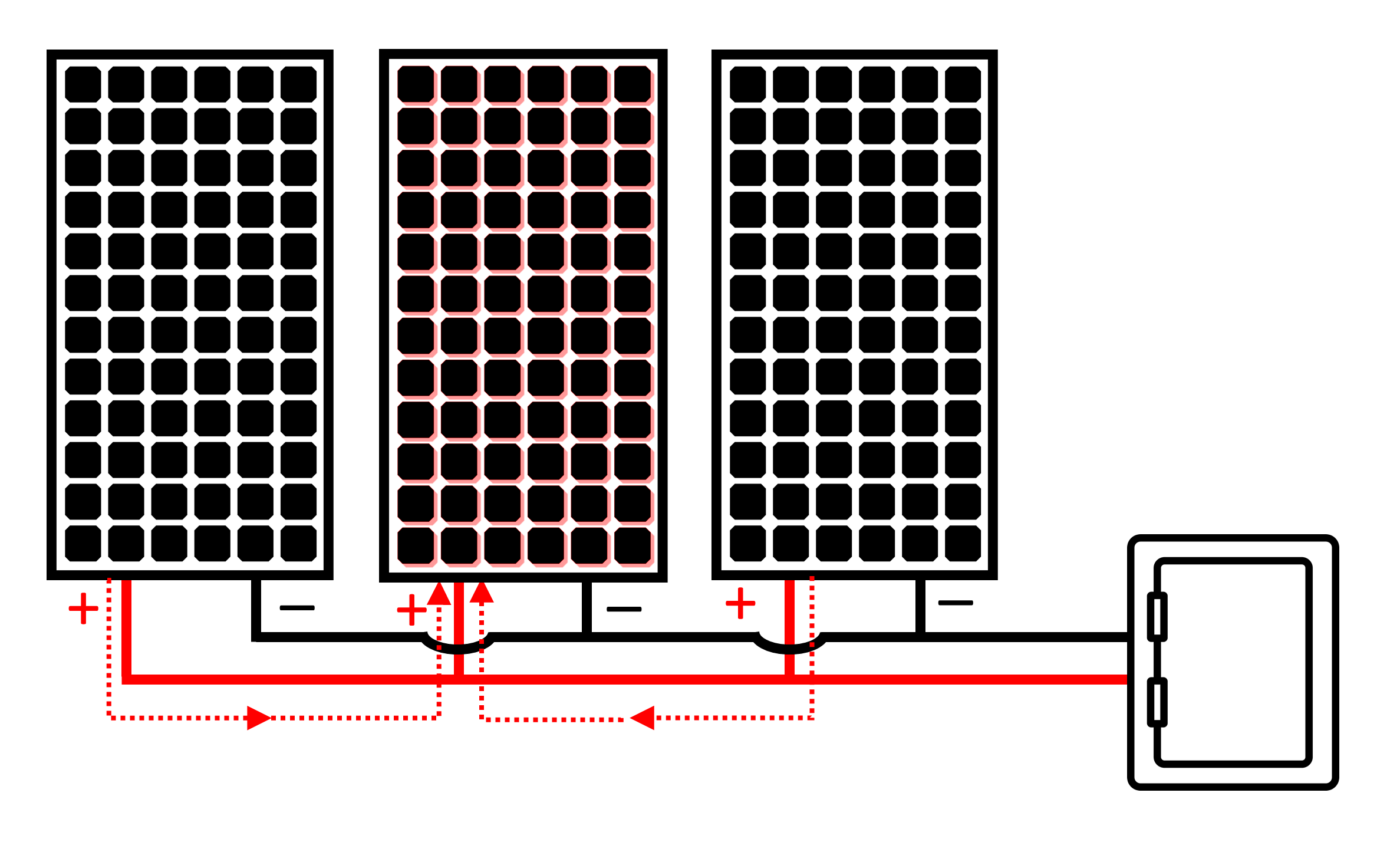
More Parallel Strings: Subsection 690.9(A)(2) of the NEC®, on the other hand, requires overcurrent protection for any circuit conductor that connects a current-limited supply (e.g., PV module) to a power source having a maximum circuit current exceeding the conductor’s ampacity. Additional circuits could backfeed a faulty circuit, overloading its conductors with more current than they were sized for.
Electricity coming from parallel modules could, for instance, backfeed into a faulty, damaged, or shaded module (Figure 13). In that case, the faulty module would absorb the total short circuit current coming the remaining modules. The combined current coming from the parallel modules could exceed the ampacity of the conductor (see nominal ampacity calculations in Step #3-1), as well as the maximum series fuse rating that’s specified for the faulty module (see Figure 9).
Under this fault condition, the conductors and the PV modules would be subject to damage and/or risk of fire, thus requiring overcurrent protection. A short circuit in one of the modules would trip the OCPD – cutting the flow of current before it becomes a hazard.
Inverter Output: Overcurrent protection for the inverter output circuit will protect the conductors on the AC side of the system based on the system type (Figure 14). An inverter circuit breaker can be used with stand-alone inverters, while the overcurrent protection for interactive systems will depend on the location of the utility interconnection.
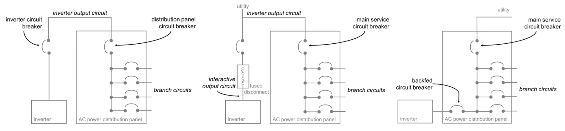
Supply-side connections may use a service-rated fused disconnect to protect the system from utility-service faults with current-limiting OCPDs having a high maximum current rating. Load-side connections, on the other hand, may be connected to the AC distribution panel through a back-fed circuit breaker that permits current flow in either direction. The back-fed circuit breaker protects the branch circuits from the inverter, while the panel’s main service circuit breaker protects the service conductors.
OCPD Ratings [NEC® 690.9(B)]
NEC® Subsection 690.9(B) addresses various OCPD requirements for PV circuits, with the OCPD ratings based on the ampacity of the conductors that they protect. As such, the sizing of an OCPD for a PV circuit will follow a procedure similar to calculating the maximum current of a conductor (Step #2-1) and conductor ampacity (Steps #3-1 and #3-4).
Step 5-1: Calculate maximum circuit current as performed in Step #2-1. Again, the short-circuit current of a PV module will deviate from its nameplate rating due to any fluctuations in the solar intensity. Short-circuit current will be higher than the nameplate rating when irradiance exceeds STC (1,000 W/m² under STC).
Assuming all parallel strings have equal current, the maximum circuit current (Imax) of a PV source circuit, or PV output circuit, can be calculated by multiplying the rated short-circuit current (Isc) by the number of parallel strings (np), by an overcurrent safety factor (ηi) of 1.25. The Imax for an inverter input circuit is based on the inverter’s output power (P), minimum operating voltage (Vmin), and inverter efficiency (η). The Imax of an inverter output circuit, on the other hand, is calculated by dividing the inverter’s power output (P) by its operating voltage (VAC). Review Step #2-1 for more information.
PV Source or Output: Imax = Isc × np × ηi
Inverter Input: Imax = Iin = P ÷ Vmin ÷ η
Inverter Output : Imax = Iout = P ÷ VAC
Step 5-2: Calculate the nominal ampacity as performed in Step #3-1. OCPDs shall carry not less than 125% of the maximum circuit current in accordance with NEC® Subsection 690.8(B); although exceptions are permitted for equipment listed for operation at 100% of its rating. Overcurrent protection is sized for 125% of the maximum current since all PV system currents are considered continuous for the purpose of OCPD sizing. In this case, nominal ampacity (Inom) is based on the maximum current (Imax) multiplied by a safety factor (ηc) of 1.25 (125%) to account for a continuous electrical current (3 hours in duration) as follows:
Inom = Imax × 1.25
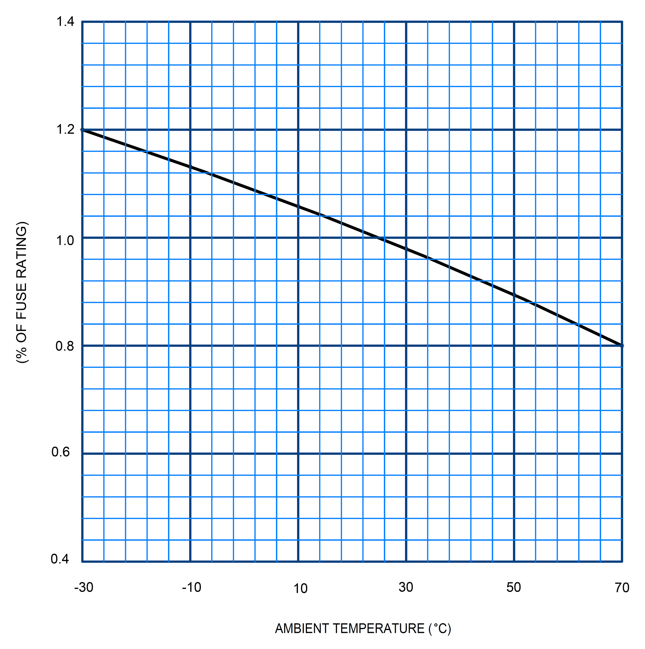
Step 5-3: Derate nominal ampacity to account for ambient temperatures that deviate from the STC of 25°C (77°F) under which nameplate ratings are specified. While temperature correction factors are often applied with temperatures over 40°C (104°F), correction factors may be unnecessary if the duration of exposure is under 2 hours. OCPDs can also be installed in shaded areas to mitigate heat exposure. Prolonged exposure to high temperatures could otherwise accelerate fuse element melting – causing nuisance trips below the nameplate rating.
If an OCPD is exposed to sustained temperatures above 40°C, then apply a correction factor to avoid nuisance trips. Determine the temperature derating coefficient based on the sustained ambient temperature using a derating chart from the OCPD manufacturer (Figure 15). Divide nominal ampacity (Inom) by the derating coefficient (CD) to determine the derated ampacity (Id) as follows:
Id = Inom ÷ CD
If derating is applied, the nameplate rating of the OCPD must not exceed the ampacity of the conductors or the maximum series fuse rating of the PV modules when working with PV source circuits.
Step 5-4: Determine nameplate rating. If the derated ampacity (Id) is not a readily-available OCPD rating, NEC® Subsection 690.8(B) permits the selection of the next highest available rating. For example, if the OCPD ampacity is calculated to be 13.5A, then a 15A fuse could be used as it is the next highest available rating.
Step 5-5: Check OCPD rating. The ampacity of a conductor in a circuit with overcurrent protection must be equal to, or greater than, the rating of the OCPD that’s protecting it. An OCPD within a PV source-circuit, for example, must not exceed the maximum series fuse rating of the PV module(s). The maximum series fuse rating is the maximum current that a module can accept before it overheats and becomes a fire hazard. This rating is commonly found on a module’s specification label (Figure 9).
Consequently, the smallest wire for a given circuit corresponds to a temperature-derated ampacity that equals the OCPD rating. If the temperature-derated ampacity of the conductor (after conditions of use have been applied) is less than the OCPD rating, then a larger conductor is needed to ensure safety. Higher OCPD ratings will not protect the PV module.
Conclusions
A careful review of this publication will help you understand some of the important electrical characteristics, essential wiring requirements, and critical considerations for overcurrent protection within PV system circuits. While it provides a brief overview of sizing, selecting and integrating the wiring and overcurrent protection, be sure to consult a licensed contractor or electrician before designing and installing a solar electric system. Qualified installers must understand all applicable electrical codes, regulations and recommendations, including safe working and installation practices for code-compliant electrical integration.
References
- ASHRAE. (2017). ASHRAE® Handbook – Fundamentals. American Society of Heating Refrigerating and Air-Conditioning Engineers, Inc. SI edition. https://app.knovel.com/kn/resources/kpASHRAEQ1/toc
- FSEC. (2023). Solar Reference Map. The Florida Solar Energy Center. Retrieved from https://energyresearch.ucf.edu/solar-certification/solar-reference-map/
- NFPA. (2022). NFPA 70: National Electrical Code 2023. National Fire Protection Association. https://www.nfpa.org/codes-and-standards/all-codes-and-standards/list-of-codes-and-standards/detail?code=70
Funding acknowledgement

This material is based upon work supported by the National Institute of Food and Agriculture, U.S. Department of Agriculture, through the Northeast Sustainable Agriculture Research and Education program under subaward # ENE20-165-34268
Appendix
| Temperature Rating of Copper Conductor | Temperature Rating of Aluminum Conductor | |||||
|---|---|---|---|---|---|---|
| Size (AWG) | 60°C Rated (140°F)ᵃ | 75°C Rated (167°F)ᵇ | 90°C Rated (194°F)ᶜ | 60°C Rated (140°F)ᵃ | 75°C Rated (167°F)ᵇ | 90 °C Rated (194°F)ᶜ |
| Conductors in a raceway, cable, conduit, or earth (directly buried) | ||||||
| 18 | - | - | 14 | - | - | - |
| 16 | - | - | 18 | - | - | - |
| 14 | 15 | 20 | 25 | - | - | - |
| 12 | 20 | 25 | 30 | 15 | 20 | 25 |
| 10 | 30 | 35 | 40 | 25 | 30 | 35 |
| 8 | 40 | 50 | 55 | 35 | 40 | 45 |
| 6 | 55 | 65 | 75 | 40 | 50 | 55 |
| 4 | 70 | 85 | 95 | 55 | 65 | 75 |
| 3 | 85 | 100 | 115 | 65 | 75 | 85 |
| 2 | 95 | 115 | 130 | 75 | 90 | 100 |
| 1 | 110 | 130 | 145 | 85 | 100 | 115 |
| 1/0 | 125 | 150 | 170 | 100 | 120 | 135 |
| 2/0 | 145 | 175 | 195 | 115 | 135 | 150 |
| 3/0 | 165 | 200 | 225 | 130 | 155 | 175 |
| 4/0 | 195 | 230 | 260 | 150 | 180 | 205 |
| Temperature Rating of Copper Conductor | Temperature Rating of Aluminum Conductor | |||||
|---|---|---|---|---|---|---|
| Size (AWG) | 60°C Rated (140°F)ᵃ | 75°C Rated (167°F)ᵇ | 90°C Rated (194°F)ᶜ | 60°C Rated (140°F)ᵃ | 75°C Rated (167°F)ᵇ | 90 °C Rated (194°F)ᶜ |
| Conductors in free air | ||||||
| 18 | - | - | 18 | - | - | - |
| 16 | - | - | 24 | - | - | - |
| 14 | 25 | 30 | 35 | - | - | |
| 12 | 30 | 35 | 40 | 25 | 30 | 35 |
| 10 | 40 | 50 | 55 | 35 | 40 | 45 |
| 8 | 60 | 70 | 80 | 45 | 55 | 60 |
| 6 | 80 | 95 | 105 | 60 | 75 | 85 |
| 4 | 105 | 125 | 140 | 80 | 100 | 115 |
| 3 | 120 | 145 | 165 | 95 | 115 | 130 |
| 2 | 140 | 170 | 190 | 110 | 135 | 150 |
| 1 | 165 | 195 | 220 | 130 | 155 | 175 |
| 1/0 | 195 | 230 | 260 | 150 | 180 | 205 |
| 2/0 | 225 | 265 | 300 | 175 | 210 | 235 |
| 3/0 | 260 | 310 | 350 | 200 | 240 | 270 |
| 4/0 | 300 | 360 | 405 | 235 | 280 | 315 |
ᵃ Types: TW, UF
ᵇ Types: RHW, THHW, THW, THWN, XHHW, XHWN, USE, ZW
ᶜ Types: TBS, SA, SIS, FEP, FEPB, MI, PFA, RHH, RHW-2, THHN, THHW, THW-2, THWN-2, USE-2, XHH, XHHW, XHHW-2, XHWN, XHWN‑2, XHHN, Z, ZW-2
Note: This reprinted material is not the complete and official position of the NFPA on the referenced subject, which is represented only by the standard in its entirety.
| SIZE | CONDUCTORS | DC RESISTANCE AT 75°C | |||||||||||||
|---|---|---|---|---|---|---|---|---|---|---|---|---|---|---|---|
| Gauge | Area | Stranding | Overall | Copper | Aluminum | ||||||||||
| AWG or kcmil | mm² | circular mils | Qty | Diameter | Diameter | Area | Uncoated | Coated | |||||||
| (-) | mm | in | mm | in | mm² | in² | ohm/km | ohm/kft | ohm/km | ohm/kft | ohm/km | ohm/kft | |||
| 18 | 0.823 | 1620 | 1 | - | - | 1.02 | 0.040 | 0.823 | 0.001 | 25.5 | 77.7 | 26.5 | 8.08 | 42.0 | 12.8 |
| 18 | 0.823 | 1620 | 7 | 0.39 | 0.015 | 1.16 | 0.046 | 1.06 | 0.002 | 26.1 | 7.95 | 27.7 | 8.45 | 42.8 | 13.1 |
| 16 | 1.31 | 2580 | 1 | - | - | 1.29 | 0.051 | 1.31 | 0.002 | 16.0 | 4.89 | 16.7 | 5.08 | 26.4 | 8.05 |
| 16 | 1.31 | 2580 | 7 | 0.49 | 0.019 | 1.46 | 0.058 | 1.68 | 0.003 | 16.4 | 4.99 | 17.3 | 5.29 | 26.9 | 8.21 |
| 14 | 2.08 | 4110 | 1 | - | - | 1.63 | 0.064 | 2.08 | 0.003 | 10.1 | 3.07 | 10.4 | 3.19 | 16.6 | 5.06 |
| 14 | 2.08 | 4110 | 7 | 0.62 | 0.024 | 1.85 | 0.073 | 2.68 | 0.004 | 10.3 | 3.14 | 10.7 | 3.26 | 16.9 | 5.17 |
| 12 | 3.31 | 6530 | 1 | - | - | 2.05 | 0.081 | 3.31 | 0.005 | 6.34 | 1.93 | 6.57 | 2.01 | 10.45 | 3.18 |
| 12 | 3.31 | 6530 | 7 | 0.78 | 0.030 | 2.32 | 0.092 | 4.25 | 0.006 | 6.50 | 1.98 | 6.73 | 2.05 | 10.69 | 3.25 |
| 10 | 5.261 | 10380 | 1 | - | - | 2.588 | 0.102 | 5.26 | 0.008 | 3.984 | 1.21 | 4.148 | 1.26 | 6.561 | 2.00 |
| 10 | 5.261 | 10380 | 7 | 0.98 | 0.038 | 2.95 | 0.116 | 6.76 | 0.011 | 4.070 | 1.24 | 4.226 | 1.29 | 6.679 | 2.04 |
| 8 | 8.367 | 16510 | 1 | - | - | 3.264 | 0.128 | 8.37 | 0.013 | 2.506 | 0.764 | 2.579 | 0.786 | 4.125 | 1.26 |
| 8 | 8.367 | 16510 | 7 | 1.23 | 0.049 | 3.71 | 0.146 | 10.76 | 0.017 | 2.551 | 0.778 | 2.653 | 0.809 | 4.204 | 1.28 |
| 6 | 13.30 | 26240 | 7 | 1.56 | 0.061 | 4.67 | 0.184 | 17.09 | 0.027 | 1.608 | 0.491 | 1.671 | 0.510 | 2.652 | 0.808 |
| 4 | 21.15 | 41740 | 7 | 1.96 | 0.077 | 5.89 | 0.232 | 27.19 | 0.042 | 1.010 | 0.308 | 1.053 | 0.321 | 1.666 | 0.508 |
| 3 | 26.67 | 52620 | 7 | 2.20 | 0.087 | 6.60 | 0.260 | 34.28 | 0.053 | 0.802 | 0.245 | 0.833 | 0.254 | 1.320 | 0.403 |
| 2 | 33.62 | 66360 | 7 | 2.47 | 0.097 | 7.42 | 0.292 | 43.23 | 0.067 | 0.634 | 0.194 | 0.661 | 0.201 | 1.045 | 0.319 |
| 1 | 42.41 | 83690 | 19 | 1.69 | 0.066 | 8.43 | 0.332 | 55.80 | 0.087 | 0.505 | 0.154 | 0.524 | 0.160 | 0.829 | 0.253 |
| 1/0 | 53.49 | 105600 | 19 | 1.89 | 0.0074 | 9.45 | 0.372 | 70.41 | 0.109 | 0.399 | 0.122 | 0.415 | 0.127 | 0.660 | 0.201 |
| 2/0 | 67.43 | 133100 | 19 | 2.13 | 0.084 | 10.62 | 0.418 | 88.74 | 0.137 | 0.3170 | 0.0967 | 0.329 | 0.101 | 0.523 | 0.159 |
| 3/0 | 85.01 | 167800 | 19 | 2.39 | 0.094 | 11.94 | 0.470 | 111.9 | 0.173 | 0.2512 | 0.0766 | 0.2610 | 0.0797 | 0.413 | 0.126 |
| 4/0 | 107.2 | 211600 | 19 | 2.68 | 0.106 | 13.41 | 0.528 | 141.1 | 0.219 | 0.1996 | 0.0608 | 0.2050 | 0.0626 | 0.328 | 0.100 |
| 250 | 127 | - | 37 | 2.09 | 0.082 | 14.61 | 0.575 | 168 | 0.260 | 0.1687 | 0.0515 | 0.1753 |
0.0535 |
0.2778 | 0.0847 |
| 300 | 152 | - | 37 | 2.29 | 0.090 | 16.00 | 0.630 | 201 | 0.312 | 0.1409 | 0.0429 | 0.1463 | 0.0446 | 0.2318 | 0.0707 |
| 350 | 177 | - | 37 | 2.47 | 0.097 | 17.30 | 0.681 | 235 | 0.364 | 0.1205 | 0.0367 | 0.1252 | 0.0382 | 0.1984 | 0.0605 |
| 400 | 203 | - | 37 | 2.64 | 0.104 | 18.49 | 0.728 | 268 | 0.416 | 0.1053 | 0.0321 | 0.1084 | 0.0331 | 0.1737 | 0.0529 |
| 500 | 253 | - | 37 | 2.95 | 0.116 | 20.65 | 0.813 | 336 | 0.519 | 0.0845 | 0.0258 | 0.0869 | 0.0265 | 0.1391 | 0.0424 |
| 600 | 304 | - | 61 | 2.52 | 0.099 | 22.68 | 0.893 | 404 | 0.626 | 0.0704 | 0.0214 | 0.0732 | 0.0223 | 0.1159 | 0.0353 |
| 700 | 355 | - | 61 | 2.72 | 0.107 | 24.49 | 0.964 | 471 | 0.730 | 0.0603 | 0.0184 | 0.0622 | 0.0189 | 0.0994 | 0.0303 |
| 750 | 380 | - | 61 | 2.82 | 0.111 | 25.35 | 0.998 | 505 | 0.782 | 0.0563 | 0.0171 | 0.0579 | 0.0176 | 0.0927 | 0.0282 |
| 800 | 405 | - | 61 | 2.91 | 0.114 | 26.16 | 1.030 | 538 | 0.834 | 0.0528 | 0.0161 | 0.0544 | 0.0166 | 0.0868 | 0.0265 |
| 900 | 456 | - | 61 | 3.09 | 0.122 | 27.79 | 1.094 | 606 | 0.940 | 0.0470 | 0.0143 | 0.0481 | 0.0147 | 0.0770 | 0.0235 |
| 1000 | 507 | - | 61 | 3.25 | 0.128 | 29.26 | 1.152 | 673 | 1.042 | 0.0423 | 0.0129 | 0.0434 | 0.0132 | 0.0695 | 0.0212 |
| 1250 | 633 | - | 91 | 2.98 | 0.117 | 32.74 | 1.289 | 842 | 1.305 | 0.0338 | 0.0103 | 0.0347 | 0.0106 | 0.0554 | 0.0169 |
| 1500 | 760 | - | 91 | 3.26 | 0.128 | 35.86 | 1.412 | 1011 | 1.566 | 0.02814 | 0.00858 | 0.02814 | 0.00883 | 0.0464 | 0.0141 |
| 1750 | 887 | - | 127 | 2.98 | 0.117 | 38.76 | 1.526 | 1180 | 1.829 | 0.02410 | 0.00735 | 0.02410 | 0.00756 | 0.0397 | 0.0121 |
| 2000 | 1013 | - | 127 | 3.19 | 0.126 | 41.45 | 1.632 | 1349 | 2.092 | 0.02109 | 0.00643 | 0.02109 | 0.00662 | 0.0348 | 0.0106 |
Note: These resistance values are valid only for the parameters given. Using conductors having coated strands, different stranding type, and, especially, other temperature changes the resistance. If the circuit you're measuring uses DC current, you can use this chart to find ohms per kft (Ω/ kft) for the wire gauge selected. For AC current, resistance is technically known as impedance, but is measured in ohms (Ω). This reprinted material is not the complete and official position of the NFPA on the referenced subject, which is represented only by the standard in its entirety.
| Maximum Voltage: Refer to “Maximum Voltage” for more info | |
| * Determine voltage correction factor (CV) using Table 3 as based on the ‘Extreme Annual Mean Minimum Design Dry Bulb Temp’ of your location using the ASHRAE Fundamentals Handbook (ASHRAE, 2017). | -11 °C → 1.16 |
| ________°C → ________ | |
| 1-1: Calculate maximum PV circuit voltage (Vmax) based on the rated open-circuit voltage of a PV module (Voc), the number of series connected modules (ns), and the voltage correction factor (CV). | 21.2 V × 16 modules × 1.16 = 393.5 V |
| ________ V × ________ modules × ________ = ________ V | |
| Maximum Current: Refer to “Maximum Current” for more info | ||
| 2-1: Calculate maximum current (Imax) of a PV source or PV output circuit by multiplying the rated short-circuit current (Isc) of the module(s), by the number of parallel strings (np), by an overcurrent safety factor (ηi) of 1.25. | PV Source / Output | 6.1 A × 2 strings × 1.25 = 15.3 A |
| ________ A × ________ strings × 1.25 = ________ A | ||
| Calculate Imax of an inverter input circuit by multiplying the inverter’s output power (P), by its minimum operating voltage (Vmin), by its efficiency (η). | Inverter Input | 3,800 W ÷ 80 V ÷ 0.967 = 49.1 A |
| ________W ÷ ________V ÷ ________ = ________ A | ||
| Calculate Imax of an inverter output circuit by dividing the inverter’s power output (P) by its operating voltage (VAC). | Inverter Output | 3,800 W ÷ 240 VAC = 15.8 A |
| ________W ÷ ________VAC = ________ V | ||
| Conductor Ampacity: Refer to “Conductor Ampacity” for more info | |
| 3-1: Calculate nominal ampacity (Inom) of each circuit, based on the maximum current (Imax), to account for the continuous electrical current using a safety factor (ηc) of 1.25 (125%). | 15.3 A × 1.25 = 19.1 A |
| ________ A × 1.25 =________ A | |
| 3-2: Determine the temperature correction factor (CT) using Table 4 based on the hottest local temperature on record for your location (FSEC, 2023) and any rooftop temperature adder (310.15(B)(2)). | 34 °C + 33 °C = 67 °C → 0.58 |
| ________°C +________°C = ________°C → ________ | |
| 3-3: Determine conductor-in-conduit factor (CC) using Table 5 based on the number of current-carrying conductors running within the conduit. | 4 conductors → 0.8 |
| ________ conductors → ________ | |
| 3-4: Calculate derated ampacity (Id) based on the nominal ampacity (Inom), as well as the temperature-based correction factor (CT) and conduit-based correction factor (CF). | 19.1 A ÷ 0.58 ÷ 0.8 = 41.2 A |
| ________A ÷ ________ ÷ ________ = ________ A | |
| 3-5: Determine the wire size that meets or exceeds the derated ampacity of the circuit using Table A1 for current-carrying conductors in a raceway, cable, conduit, or earth; or in free air. | Raceway, cable, conduit, or earth; USE-2; 41.2 A → 8 AWG |
| ________ ; ________ ; ________ A → ________ AWG | |
| Wire Length: Refer to Wire Length for more info | ||
| 4-1: Determine wire resistance (R) using Table A2 based on wire size (AWG or kcmil), conductor material (copper or aluminum), and conductor composition (stranded or solid). | 8 AWG; copper; stranded → 0.778 Ω/ kft | |
| ________AWG ; ________ ; ________ → ________ Ω/ kft | ||
| 4-2: Calculate max operating current (Iop) based on the optimum operating current (Imp) of the module or inverter, as well as the number of parallel modules or strings (np) in the array. | PV Source / Output | 5.7 A × 2 strings = 11.4 A |
| ________A × ________ strings = ________ A | ||
| Inverter Input | 15.8 A = 15.8 A | |
| ________ A = ________ A | ||
| 4-3: Determine the roundtrip circuit length (L) based on the complete distance of each wire path (D). Multiply by 2 for DC-side and split-phase AC. Multiply by 1.732 for 3-phase AC. | PV Source / Output and Split Phase | 216 ft × 2 = 432 ft |
| ________ ft × 2 = ________ ft | ||
| Inverter Output (3- Phase) | 35 ft × 1.732 = 60.6 ft | |
| ________ ft × 1.732 = ________ ft | ||
| 4-4: Calculate voltage drop (Vdrop) by multiplying maximum operating current (Iop), by wire resistance (R), by circuit length (L). | 11.4 A × 0.778 Ω/kft × 0.432 kft = 3.8 V | |
| ________ A = ________Ω/ kft ×________ kft = ________V | ||
| * Calculate operating drop (Vop) based on the voltage at maximum power (Vmp) and the number of series-connected modules (ns). | 17.7 V × 16 modules = 283.2 V | |
| ________ V × ________ modules = ________ V | ||
| 4-5: Calculate the percent voltage drop (V%) by dividing voltage drop (Vdrop) by operating voltage (Vop). Multiply by 100 for percent. | 100 × 3.8 V ÷ 283.2 V = 1.34% | |
| 100 × ________ V ÷ ________ V = ________ % | ||
| OCPD Rating: Refer to OCPD Ratings for more info | ||
| 5-1: Calculate maximum current (Imax) of a PV source or PV output circuit by multiplying short-circuit current (Isc), by number of parallel strings (np), by overcurrent safety factor (ηi) of 1.25. | PV Source /Output | 6.1 A × 2 strings × 1.25 = 15.3 A |
| ________ A × ________ strings × 1.25 = ________ A | ||
| Calculate Imax of an inverter input circuit by multiplying the inverter’s output power (P), by its minimum operating voltage (Vmin), by its efficiency (η). | Inverter Input | 3,800 W ÷ 80 V ÷ 0.967 = 49.1 A |
| ________ W ÷ ________ V ÷________ = ________ A | ||
| Calculate Imax of an inverter output circuit by dividing the inverter’s power output (P) by its operating voltage (VAC). | Inverter Output | 3,800 W ÷ 240 VAC = 15.8 A |
| ________ W ÷ ________ VAC = ________ A | ||
| 5-2: Calculate nominal ampacity (Inom) by multiplying maximum current (Imax) by a safety factor (ηc) of 1.25. | 15.3 A × 1.25 = 19.1 A |
|
| ________ A × 1.25 = ________ A | ||
| * Assess derating coefficient (CD) based on ambient temp & manufactuer’s chart (Fig 15). | 50°C → 0.895 | |
| ________ °C → ________ | ||
| 5-3: Calculate derated ampacity (Id) by dividing nominal ampacity (Inom) by derating coefficient (CD). | 19.1 A ÷ 0.895 = 21.3 A | |
| ________ A ÷ ________ = ________ A | ||
| 5-4: Determine OCPD rating by selecting the next highest available rating relative to the derated ampacity (Id). | 21.3 A → 25 A | |
| ________ A → ________ A | ||
| 5-5: Check OCPD rating to ensure that it’s less than, or equal to, the ampacity of the conductor that it’s protecting. | 25 A ≤ 55 A | |
| ________ A ≤ ________ A | ||
All images by the author
DREW SCHIAVONE, PH.D.
dschiavo@umd.edu
This publication, Working on Solar Wiring and Fusing (FS-2023-0676) is a part of a collection produced by the University of Maryland Extension within the College of Agriculture and Natural Resources.
The information presented has met UME peer-review standards, including internal and external technical review. For help accessing this or any UME publication contact: itaccessibility@umd.edu
For more information on this and other topics, visit the University of Maryland Extension website at extension.umd.edu
University programs, activities, and facilities are available to all without regard to race, color, sex, gender identity or expression, sexual orientation, marital status, age, national origin, political affiliation, physical or mental disability, religion, protected veteran status, genetic information, personal appearance, or any other legally protected class.
When citing this publication, please use the suggested format below:
Schiavone, D. (2023). Working on Solar Wiring and Fusing (FS-2023-0676), University of Maryland Extension. go.umd.edu/FS-2023-0676.
Related Resources
-
Solar Module Guide >
Solar Module Guide > -
Working on Solar Design and System Sizing (FS-2023-0655) >
Working on Solar Design and System Sizing (FS-2023-0655) > -
Working on Solar Panels and Power Output (FS-2022-0646) >
Working on Solar Panels and Power Output (FS-2022-0646) >